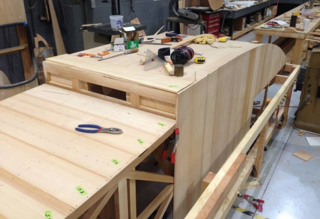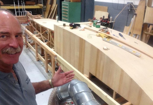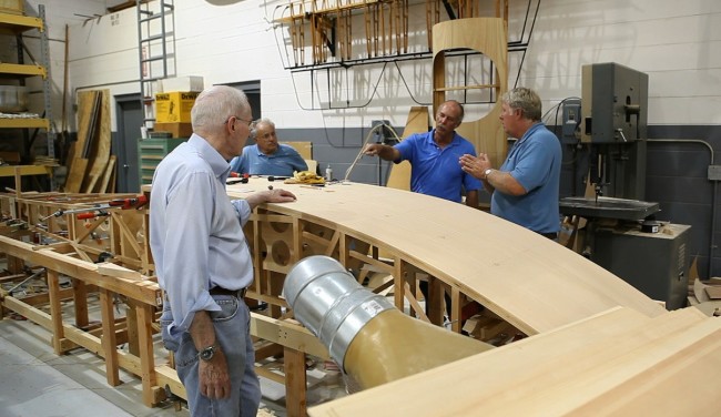
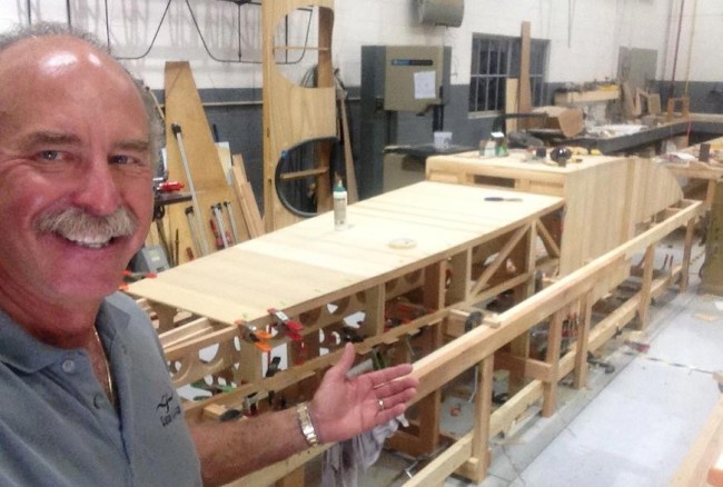
Our own Ken Kellett just got back from vacation and is beginning to plank the Benoist hull in earnest now as these updates from Kermit show:

1

The front step area gets three layers of 1/4″ x 4″ spruce and the sides and bottom aft of the step get 2 layers. Here’s a closer view of the step area:

2

Here’s a shot from the front:

3

The side strips begin vertical and the next layer goes forward and aft. The bottom begins forward and aft because it ultimately gets three layers. Originally, in the construction of old boats and early seaplanes, fabric would have been glued under the last layer of wood to help seal the hull. Because you won’t be able to see it, we will use fiberglass cloth and epoxy glue, which is stronger and should seal it better.

In addition to Ken, we have four others focusing on cables, turnbuckles, a cable tension tester, the fuel tank, and the drive system. The engine guy up north is making progress and will also do the radiator.

Five months and counting! Tick… tick… tick…

We’re sorry about not posting for a bit. We’ve been rolling out a new website that is a vast improvement over our old one. We were going to move the blog of there eventually, but that’s taking longer than we thought, and you guys deserve an update, so here we go!
We had a meeting yesterday on where were are relative to getting our Benoist reproduction ready for the 100th Anniversary flight on January 1, 2014.

The clock is ticking and we’re beginning to feel we’re a bit behind the power curve.

A-Benoist-Progress

We’ve mobilized everyone in the Aircraft Department to begin making this our PRIMARY focus, as we’ve still got a lot of work to do. Anslo, our built from scratch Roberts engine has also become the top priority at the shop where its being constructed.
We got some sad news from our friends that built a “Lark of Duluth” replica. This was the airplane that eventually became our Tony Jannus airplane and flew during a Duluth, MN Festival during the summer of 1913.

B-Benoist-Progress

They missed flying their airplane for their 100th Anniversary event but finally got a chance to fly it last week . . . for about ten seconds!

It seems the pressure is on both our Fantasy of Flight CREW as builders . . . and on KERMIT as a pilot!

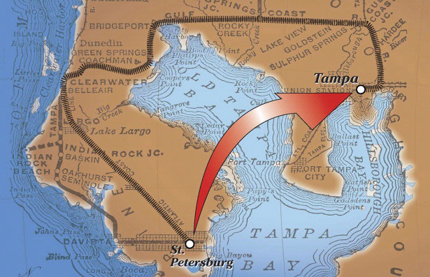
When people read the story of the first airline flight, they often wonder at the travel time of 23 minutes for a short trip across the bay. Why on earth would people pay for a 23 minute flight?

The reason becomes clear when you understand what travel options were available in 1914. Back then, there was no such thing as a “quick trip across the bay.” With no bridges and brand new automotive technology, a drive was an uncomfortable 20 hours! A somewhat more luxurious rail trip could range anywhere between 4 and 12 hours, and even the direct route across the water by steamboat would take you more than two hours.

Posted by on Wednesday, January 2, 2013
Filed in: Benoist 2014
commentsPost a comment →

Benoist Visiting the Lark

The Duluth Aviation Institute is building their own replica of “The Lark of Duluth” which was the genesis of the Benoist Type XIV that we are replicating for the Benoist 2014 project, so we are comparing notes and swapping information with them as both projects progress. Their first flight will be about six months before ours, so we thought it would be good to drop in on them and check on their progress as 2012 draws to a close.

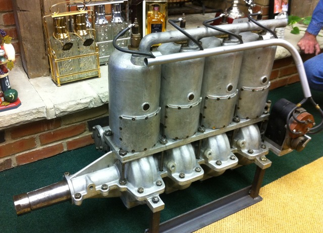
The Benoist project we’re building to recreate the 100th anniversary of the first scheduled airplane airline flight by Tony Jannus uses a six-cylinder two-cycle 75hp Roberts engine.

We know of only seven in the world and there are none to be purchased. This is one of two 4-cylinder 50hp Roberts engines I found and acquired.

We were able to borrow a six-cylinder engine from Old Rhinebeck Aerodrome that Cole Palen had acquired years ago to reverse-engineer. It had been in a crash and the case had been welded in several places.

Here’s a view of the back end with the gears for the single magneto, water pump and rotary valve induction tube.
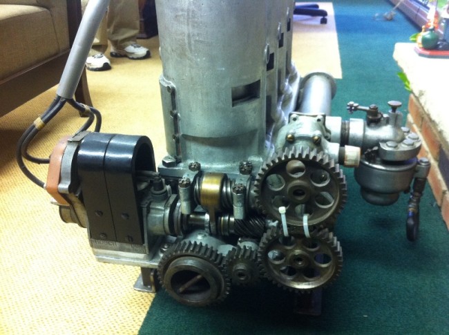
The 75hp six-cylinder engine has two more cylinders (12 ½ hp per cylinder) than the 50hp four-cylinder and uses two of the same carburetors.
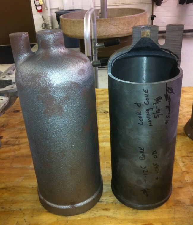
Here’s a rough cylinder liner casting on the left. The one on the right has been machined and the top partially cut out to check for proper thickness. It was actually too thin in one spot and the casting pattern had to be adjusted to compensate. Any bad parts and pieces can be melted back into the pot and used in a future attempt.
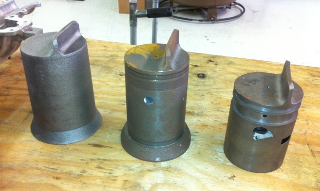
Here are steps from left to right in casting and machining the cast iron pistons.
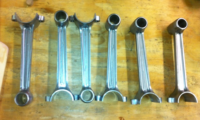
Here are six connecting rods for one engine. The big end connects to the crankshaft with two bolts and another curved piece and the little end connects to a piston with a piston pin. Each assembly will go up and down in the cast iron cylinder liner twenty times a second!.
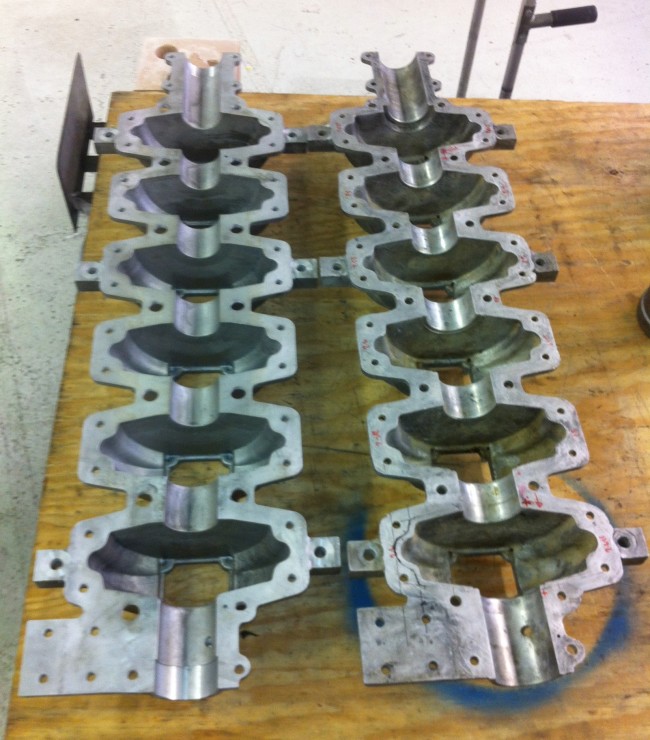
Here are lower crankcase halves. They were easier to make than the upper halves and were made first. The one on the right is from the borrowed original engine and the one on the left is newly made. The square tab at the lower left of each is where the magneto bolts on.
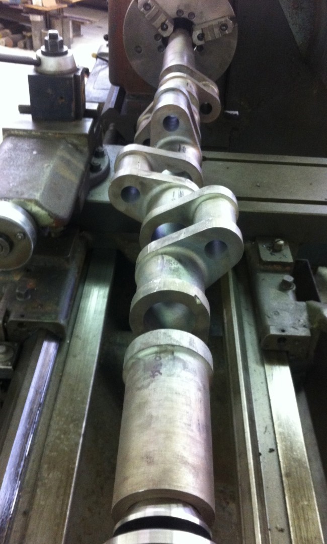
Here, the crankshaft is set up on a lathe for final machining. This started life as a 900 lb. solid billet. After much whittling down, and two sessions of annealing, it will end up weighing about 48 lbs.!

So what do you think of the progress so far?!
1 2 3 4